SERIAL COMMUNICATION
BASICS OF SERIAL COMMUNICATION:
Computers transfer data in two ways:
- Parallel
- Often 8 or more lines (wire conductors) are used to transfer data to a device that is only a few feet away
- Serial
- To transfer to a device located many meters away, the serial method is used
- The data is sent one bit at a time
- At the transmitting end, the byte of data must be converted to serial bits using parallel-in-serial-out shift register
- At the receiving end, there is a serialin- parallel-out shift register to receive the serial data and pack them into byte
- When the distance is short, the digital signal can be transferred as it is on a simple wire and requires no modulation
- If data is to be transferred on the telephone line, it must be converted from 0s and 1s to audio tones
- This conversion is performed by a device called a modem, “Modulator/demodulator”
Methods of Serial Communication:
Serial data communication uses two methods
- Synchronous method transfers a block of data at a time
- Asynchronous method transfers a single byte at a time
Half- and Full- Duplex Transmission
If data can be transmitted and received, it is a duplex transmission
- If data transmitted one way a time, it is referred to as half duplex
- If data can go both ways at a time, it is full duplex
- This is contrast to simplex transmission

Data Transfer Rate
- The rate of data transfer in serial data communication is stated in bps (bits per second)
- Another widely used terminology for bps is baud rate
- It is modem terminology and is defined as the number of signal changes per second
- In modems, there are occasions when a single change of signal transfers several bits of data
Example:
With XTAL = 11.0592 MHz, find the TH1 value needed to have the following baud rates. (a) 9600 (b) 2400 (c) 1200
Solution:
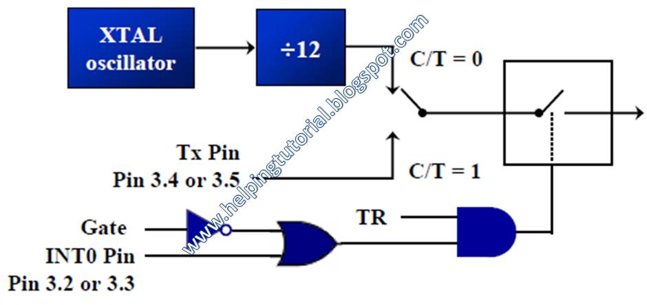
The machine cycle frequency of 8051 = 11.0592 / 12 = 921.6 kHz, and 921.6 kHz / 32 = 28,800 Hz is frequency by UART to timer 1 to set baud rate.
- 28,800 / 3 = 9600 where -3 = FD (hex) is loaded into TH1
- 28,800 / 12 = 2400 where -12 = F4 (hex) is loaded into TH1
- 28,800 / 24 = 1200 where -24 = E8 (hex) is loaded into TH1
Notice that dividing 1/12 of the crystal frequency by 32 is the default value upon activation of the 8051 RESET pin.
SBUF Register
- SBUF is an 8-bit register used solely for serial communication
- For a byte data to be transferred via the TxD line, it must be placed in the SBUF register
- The moment a byte is written into SBUF, it is framed with the start and stop bits and transferred serially via the TxD line
- SBUF holds the byte of data when it is received by 8051 RxD line
- When the bits are received serially via RxD, the 8051 deframes it by eliminating the stop and start bits, making a byte out of the data received, and then placing it in SBUF
Example:
MOV SBUF,#’D’ ;load SBUF=44h, ASCII for ‘D’
MOV SBUF,A ;copy accumulator into SBUF
MOV A,SBUF ;copy SBUF into accumulator
SCON Register
SCON is an 8-bit register used to program the start bit, stop bit, and data bits of data framing, among other things
SM0 | SCON.7 | Serial port mode specifier |
SM1 | SCON.6 | Serial port mode specifier |
SM2 | SCON.5 | Used for multiprocessor communication |
REN | SCON.4 | Set/cleared by software to enable/disable reception |
TB8 | SCON.3 | Not widely used |
RB8 | SCON.2 | Not widely used |
TI | SCON.1 | Transmit interrupt flag. Set by HW at the begin of the stop bit mode 1. And cleared by SW |
RI | SCON.0 | Receive interrupt flag. Set by HW at the begin of the stop bit mode 1. And cleared by SW |
SM0, SM1
- They determine the framing of data by specifying the number of bits per character, and the start and stop bits
- Only MODE1 is of our interest.
SM0 | SM1 | |
0 | 0 | Serial Mode 0 |
0 | 1 | Serial Mode 1, 8-bit data, 1 stop bit, 1 start bit |
1 | 0 | Serial Mode 2 |
1 | 1 | Serial Mode 3 |
SM2
- This enables the multiprocessing capability of the 8051
REN (receive enable)
- It is a bit-adressable register
- When it is high, it allows 8051 to receive data on RxD pin
- If low, the receiver is disable
TI (transmit interrupt)
- When 8051 finishes the transfer of 8-bit character
- It raises TI flag to indicate that it is ready to transfer another byte
- TI bit is raised at the beginning of the stop bit
RI (receive interrupt)
- When 8051 receives data serially via RxD, it gets rid of the start and stop bits and places the byte in SBUF register
- It raises the RI flag bit to indicate that a byte has been received and should be picked up before it is lost
- RI is raised halfway through the stop bit
Programming Serial Data Transmitting
In programming the 8051 to transfer character bytes serially
- TMOD register is loaded with the value 20H, indicating the use of timer 1 in mode 2 (8-bit auto-reload) to set baud rate
- The TH1 is loaded with one of the values to set baud rate for serial data transfer
- The SCON register is loaded with the value 50H, indicating serial mode 1, where an 8- bit data is framed with start and stop bits
- TR1 is set to 1 to start timer 1
- TI is cleared by CLR TI instruction
- The character byte to be transferred serially is written into SBUF register
- The TI flag bit is monitored with the use of instruction JNB TI,xx to see if the character has been transferred completely
- To transfer the next byte, go to step 5
Example:
Write a program for the 8051 to transfer letter “A” serially at 4800 baud, continuously.
Solution:
MOV TMOD,#20H ;timer 1,mode 2(auto reload)
MOV TH1,#-6 ;4800 baud rate
MOV SCON,#50H ;8-bit, 1 stop, REN enabled
SETB TR1 ;start timer 1
AGAIN:
MOV SBUF,#”A” ;letter “A” to transfer
HERE:
JNB TI,HERE ;wait for the last bit
CLR TI ;clear TI for next char
SJMP AGAIN ;keep sending A
Example:
Write a program for the 8051 to transfer “YES” serially at 9600 baud, 8-bit data, 1 stop bit, do this continuously
Solution:
MOV TMOD,#20H ;timer 1,mode 2(auto reload)
MOV TH1,#-3 ;9600 baud rate
MOV SCON,#50H ;8-bit, 1 stop, REN enabled
SETB TR1 ;start timer 1
AGAIN:
MOV A,#”Y” ;transfer “Y”
ACALL TRANS
MOV A,#”E” ;transfer “E”
ACALL TRANS
MOV A,#”S” ;transfer “S”
ACALL TRANS
SJMP AGAIN ;keep doing it
;serial data transfer subroutine
TRANS:
MOV SBUF,A ;load SBUF
HERE:
JNB TI,HERE ;wait for the last bit
CLR TI ;get ready for next byte
Importance of TI Flag
The steps that 8051 goes through in transmitting a character via TxD
- The byte character to be transmitted is written into the SBUF register
- The start bit is transferred
- The 8-bit character is transferred on bit at a time
- The stop bit is transferred
- It is during the transfer of the stop bit that 8051 raises the TI flag, indicating that the last character was transmitted
- By monitoring the TI flag, we make sure that we are not overloading the SBUF
- If we write another byte into the SBUF before TI is raised, the untransmitted portion of the previous byte will be lost
- After SBUF is loaded with a new byte, the TI flag bit must be forced to 0 by CLR TI in order for this new byte to be transferred
By checking the TI flag bit, we know whether or not the 8051 is ready to transfer another byte
- It must be noted that TI flag bit is raised by 8051 itself when it finishes data transfer
- It must be cleared by the programmer with instruction CLR TI
- If we write a byte into SBUF before the TI flag bit is raised, we risk the loss of a portion of the byte being transferred
The TI bit can be checked by
- The instruction JNB TI,xx
- Using an interrupt
Programming Serial Data Receiving
In programming the 8051 to receive character bytes serially
- TMOD register is loaded with the value 20H, indicating the use of timer 1 in mode
- (8-bit auto-reload) to set baud rate
- TH1 is loaded to set baud rate
- The SCON register is loaded with the value 50H, indicating serial mode 1, where an 8- bit data is framed with start and stop bits
- TR1 is set to 1 to start timer 1
- RI is cleared by CLR RI instruction
- The RI flag bit is monitored with the use of instruction JNB RI,xx to see if an entire character has been received yet
- When RI is raised, SBUF has the byte, its contents are moved into a safe place
- To receive the next character, go to step 5
Example:
Write a program for the 8051 to receive bytes of data serially, and put them in P1, set the baud rate at 4800, 8-bit data, and 1 stop bit
Solution:
MOV TMOD,#20H ;timer 1,mode 2(auto reload)
MOV TH1,#-6 ;4800 baud rate
MOV SCON,#50H ;8-bit, 1 stop, REN enabled
SETB TR1 ;start timer 1
HERE:
JNB RI,HERE ;wait for char to come in
MOV A,SBUF ;saving incoming byte in A
MOV P1,A ;send to port 1
CLR RI ;get ready to receive next byte
SJMP HERE ;keep getting data
Example:
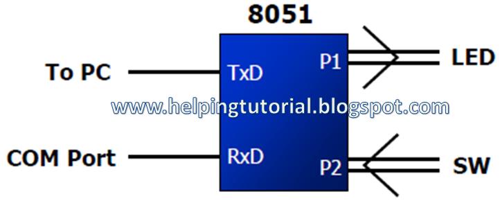
Assume that the 8051 serial port is connected to the COM port of IBM PC, and on the PC, we are using the terminal.exe program to send and receive data serially. P1 and P2 of the 8051 are connected to LEDs and switches, respectively. Write an 8051 program to (a) send to PC the message “We Are Ready”, (b) receive any data send by PC and put it on LEDs connected to P1, and (c) get data on switches connected to P2 and send it to PC serially. The program should perform part (a) once, but parts (b) and (c) continuously, use 4800 baud rate.
ORG 0
MOV P2,#0FFH ;make P2 an input port
MOV TMOD,#20H ;timer 1, mode 2
MOV TH1,#0FAH ;4800 baud rate
MOV SCON,#50H ;8-bit, 1 stop, REN enabled
SETB TR1 ;start timer 1
MOV DPTR,#MYDATA ;load pointer for message
H_1:
CLR A
MOV A,@A+DPTR ;get the character
JZ B_1 ;if last character get out
ACALL SEND ;otherwise call transfer
INC DPTR ;next one
SJMP H_1 ;stay in loop
B_1:
MOV a,P2 ;read data on P2
ACALL SEND ;transfer it serially
ACALL RECV ;get the serial data
MOV P1,A ;display it on LEDs
SJMP B_1 ;stay in loop indefinitely
;----serial data transfer. ACC has the data------
SEND:
MOV SBUF,A ;load the data
H_2:
JNB TI,H_2 ;stay here until last bit gone
CLR TI ;get ready for next char
RET ;return to caller
;----Receive data serially in ACC----------------
RECV:
JNB RI,RECV ;wait here for char
MOV A,SBUF ;save it in ACC
CLR RI ;get ready for next char
RET ;return to caller
;-----The message---------------
MYDATA: DB “We Are Ready”,0
END
Importance of RI Flag
In receiving bit via its RxD pin, 8051 goes through the following steps
- It receives the start bit
- Indicating that the next bit is the first bit of the character byte it is about to receive
- The 8-bit character is received one bit at time
- The stop bit is received
- When receiving the stop bit 8051 makes RI = 1, indicating that an entire character byte has been received and must be picked up before it gets overwritten by an incoming character
- By checking the RI flag bit when it is raised, we know that a character has been received and is sitting in the SBUF register
- We copy the SBUF contents to a safe place in some other register or memory before it is lost
- After the SBUF contents are copied into a safe place, the RI flag bit must be forced to 0 by CLR RI in order to allow the next received character byte to be placed in SBUF
- Failure to do this causes loss of the received character
By checking the RI flag bit, we know whether or not the 8051 received a character byte
- If we failed to copy SBUF into a safe place, we risk the loss of the received byte
- It must be noted that RI flag bit is raised by 8051 when it finish receive data
- It must be cleared by the programmer with instruction CLR RI
- If we copy SBUF into a safe place before the RI flag bit is raised, we risk copying garbage
- The RI bit can be checked by
- The instruction JNB RI,xx
- Using an interrupt
Doubling Baud Rate
There are two ways to increase the baud rate of data transfer
- To use a higher frequency crystal (The System Crystel is Fix)
- To change a bit in the PCON register
PCON register is an 8-bit register
- When 8051 is powered up, SMOD is zero
- We can set it to high by software and thereby double the baud rate
MOV A,PCON ;place a copy of PCON in ACC
SETB ACC.7 ;make D7=1
MOV PCON,A ;changing any other bits
Example:
Assume that XTAL = 11.0592 MHz for the following program, state (a) what this program does, (b) compute the frequency used by timer 1 to set the baud rate, and (c) find the baud rate of the data transfer.
MOV A,PCON ;A=PCON
MOV ACC.7 ;make D7=1
MOV PCON,A ;SMOD=1, double baud rate
;with same XTAL freq.
MOV TMOD,#20H ;timer 1, mode 2
MOV TH1,-3 ;19200 (57600/3 =19200)
MOV SCON,#50H ;8-bit data, 1 stop bit, RI enabled
SETB TR1 ;start timer 1
MOV A,#”B” ;transfer letter B
A_1:
CLR TI ;make sure TI=0
MOV SBUF,A ;transfer it
H_1:
JNB TI,H_1 ;stay here until the last bit is gone
SJMP A_1 ;keep sending “B” again
Solution:
(a) This program transfers ASCII letter B (01000010 binary) continuously
(b) With XTAL = 11.0592 MHz and SMOD = 1 in the above program, we have:
11.0592 / 12 = 921.6 kHz machine cycle frequency. 921.6 / 16 = 57,600 Hz frequency used by timer 1 to set the baud rate. 57600 / 3 = 19,200, the baud rate.